Shopping Cart 0
US$0.00

【EOL】BA45F5250 Development Board for NB-IoT Smoke Alarm BMAN5250DSB

US$41.96
Out of stock
Product ID
BMAN5250DSB

Note: This product has been discontinued and will not be restocked once sold out.

Looking for our Official Distributor in India?
Order directly from SPIN MODULES -
local shipping and INR payment available!
Follow Us for More Updates!
PRODUCT INSTRUCTION
  1. Power-up self-detection
    The red LED flashes once and the buzzer beeps once at power-up.
    If the board has not been calibrated, the red LED keeps lighting-up after power-on.
  2. Calibration mode
    The way to enter the calibration mode is to short the BD connector pins on the board before power-on. After entering the calibration mode, the red LED flashes once every second. If the calibration is successful, the board enters the standby mode. If the calibration is unsuccessful, the red LED will be always ON.
  3. Standby mode
    In this mode, the board work normally, the red LED flashes once every 40 seconds.
  4. Low-voltage mode
    When the power supply is lower than 3.2V, the board enters low-voltage mode, the buzzer beeps once every 40 seconds on the basic of the standby mode.
  5. Alarm mode
    When the smoke is detected, the alarm mode is entered; the red LED keeps flashing and the buzzer beeps 3 times then stops two seconds, and then cycles.
  6. Silent mode
    In alarm mode, press the TEST button to enter the silent mode, the LED keep flashing but the beep sound stops. The silent period lasts for 90 seconds.
  7. Test mode
    In standby mode, pressing the TEST button to trigger the test mode. In test mode, the board simulates the alarm status. Release the button to leave the test mode.
  8. Fault Detection
    When the IR transmitter / receiver is open circuit or short circuit, every 40 seconds the LED flashed twice and the beep sound is generated twice.
  9. Debug output
    The output port is PA2. Press the button before power on to enable the output.
    The baud rate is 115200, the data is in the standard format.
    Please refer to "HOW TO USE DEBUG OUTPUT" at the bottom of this product page.
PRODUCT FEATURES
  1. Detect smoke in the air and alert when a certain concentration is exceeded.
  2. NB-IoT (Narrow Band-Internet of Things) communication capability.
DEVELOPMENT BOARD INTRODUCTION
PROGRAMMING PINS
RESOURCES
  1. MCU : Holtek BA45F5250, Smoke Detector Flash MCU, including datasheet, package dimension, etc.
  2. Application Note: AN0540EN, BA45F5xxx Smoke Detector Integrated Analog Front End Application Notes
HOW TO USE DEBUG OUTPUT

Output the debug information through PA2 pin, please follow the below steps to get the debug data.
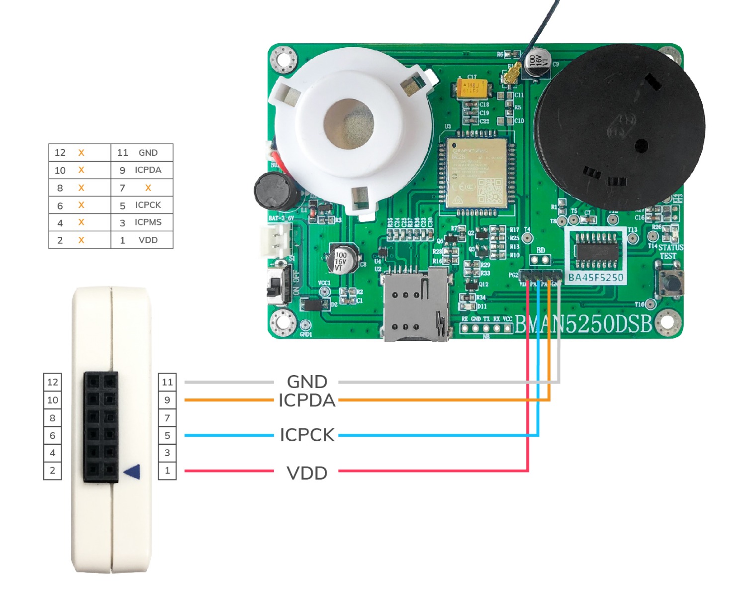
  1. Wire connection
    Connect PA2 of the board to the RX pin of your USB to serial converter.
    Connect GND of the board to the GND pin of the USB to serial converter.
    Connect the USB to serial converter to your PC.
  2. Set the power switch to off. Supply power to the board, 3V is recommended.
  3. Configure your Serial Port Monitor software to 115200bps, N81 (No parity, 8 data bits, 1 stop bit).
    Remember to choose the correct com port.
  4. With the test button pressed, switch the power switch to ON.
    Now the 35-byte debug information is shown on the Serial Port Monitor software.

Meaning of the debug information

Only part of the 35 bytes debug information are used.
The below is the meaning of each byte and the value read per our test.

Byte 0: AAh, fixed value.

Byte 1: length of the debug information, 23h

Byte 2: zero-point value. The OPA value read at the condition of transmitter turned off. 18h.

Byte 3: transmission value. The OPA valu read at the condition of transmitter turned on. 7Eh.

Byte 4: difference value. The difference of byte 3 and byte 2, with voltage compensation. 60h.

Byte 5: calibrated zero-point value.
The difference value at calibration, which is set to be zero-point value after calibration. 61h.

Byte 6: alarm trigger value.
If the measured real-time difference value minus the calibrated zero-point value (byte 5) is over this value, the alarm is triggered. 20h.

Byte 7 – Byte 8: reserved.

Byte 9: operating flag. 40h.
- Bit 0 : time-base flag
- Bit 1: standby mode flag
- Bit 2: LED flashing in standby mode flag

Byte 10: status flag. 04h.
- Bit 0: fault detection
- Bit 1: alarm mode
- Bit 2: standby mode
- Bit 3: calibration mode

Byte 11: reserved.

Byte 12: The AD value of battery, 5Ah

Byte 13: The AD value of temperature, 78h

Byte 14 – Byte 27: reserved.

Byte 28: date-year, 03h

Byte 29: date-month, 99h

Byte 30: date-day, 3Fh

Byte 31: version, high byte, 01h

Byte 32: version, low byte, 23h

Byte 33: 55h, fixed value

Byte 34: checksum

Youtube
More Information
HS Code (reference) 8473.30.00.00-6
Contact Us