The store will not work correctly in the case when cookies are disabled.
Best Modules will be closed from June 19 to June 21 in observance of Dragon Boat Festival. Please be informed that any orders placed after 15:00 PM June 17 (Taiwan time, UTC+8) will be processed on June 22.
We use cookies for optimal website use.We recommend you to allow cookies for a better user experience. Please read our privacy policy. Learn more.
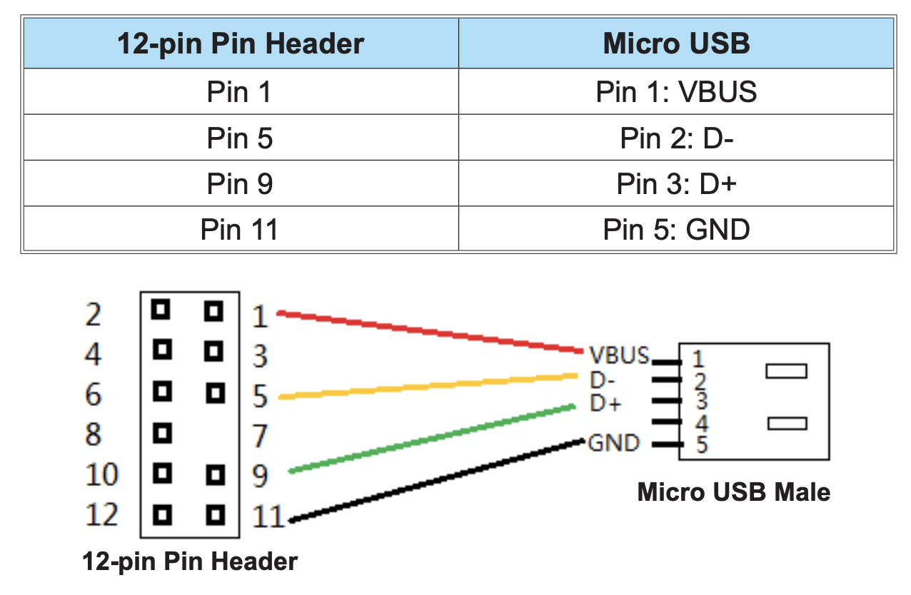
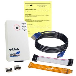
The Holtek 8-bit MCU debug adapter e-Link is 12-pin interface (2 rows x 6 pins header), the e-Link packing list includes a 12-pin flat cable to connect e-Link to the target board. That is, the target board needs to leave space for a 12-pin header. Or, leave only a 4-pin header space for the debug/programming signals (power, ground, clock, data) and use jumpers for the connection, and, remember the signals, don’t get wrong connections.
One end of this cable ESTD-206 is the 12-pin e-Link interface, and the other end is the micro USB connector. It connects the four debug/programming signals to the micro USB. The target board needs to leave a micro USB space instead of the 12-pin or 4-pin header space. And then use this cable to connect the e-Link and the target board.
Then, what should be remembered is, this micro USB is used for debug/programming, not for connecting to a computer.
Connect the e-Link debug/programming signals to a micro USB connector
Need to be used with e-Link
Cable length: 0.4m
Net Weight: 10.9g
PIN DESCRIPTION
Please note that the Micro USB interface on the DEV series development boards, such as DEV3185, DEV28SSOP185, only supports power supply and cannot be used with the product to connect to e-Link/e-LinkPro2 for debugging.